| |
| User Management |
 |
| User Management |
 |
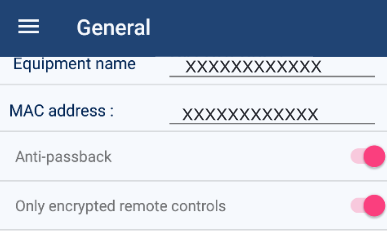
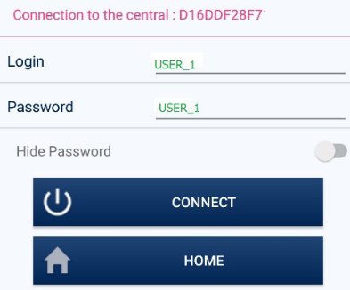
- User: You can change the default entry of USER_1 by simply overwriting the field.
- Password: You can change the default entry of USER_1 by simply overwriting the field.
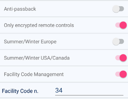
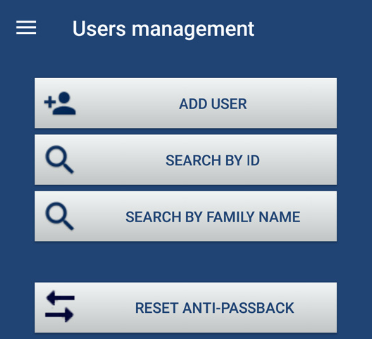
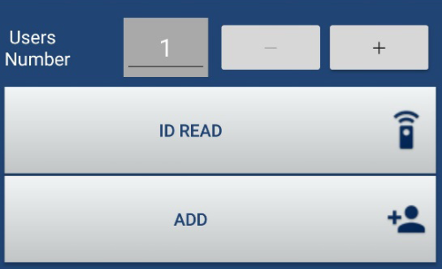
- User Management: Enables the person to; add user IDs, search by ID, search by family name and reset the anti-pass back.
- Backup: Enables the person to export or import data.
- History: Enables the person to see past events by pressing the EVENTS icon.
- Relay Commands: Enables the user to see the status of the validation inputs (VAL1/VAL2), the request to exit input (BP1/BP2) and Alarm status. They can manually activate Relay 1 and Relay
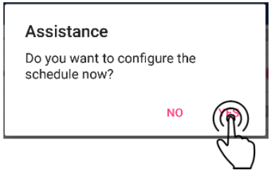
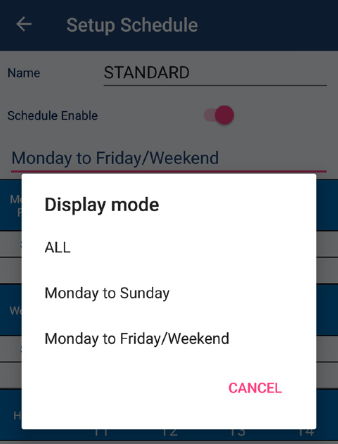
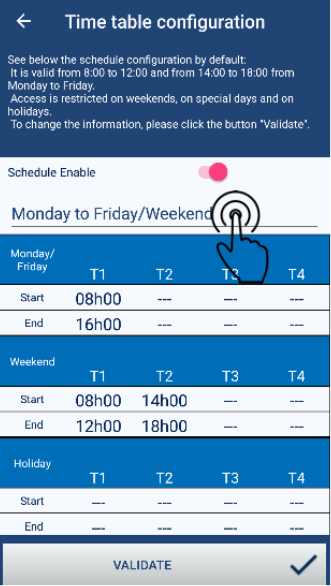
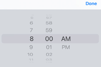
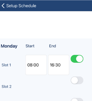
- Schedule: The person can alter schedules, holidays and special days.
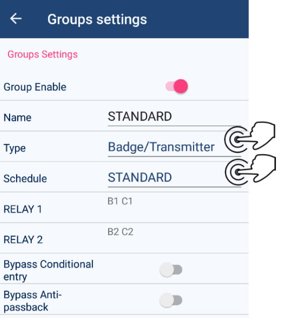
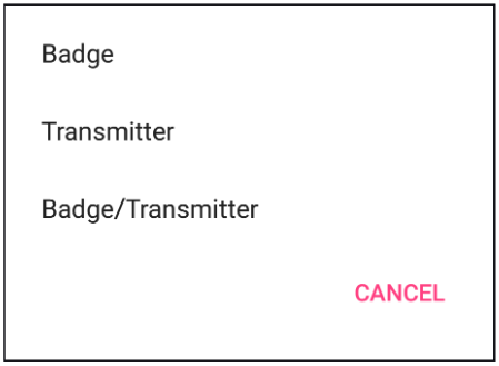
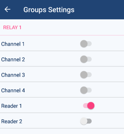
User Group Settings: The person can alter the group settings.
For site managers, they may only need the first three selections turned on; User management, Backup and History to perform their daily tasks.
To manually reset alarms, relay commands will need to be selected.
|

|
- User: You can change the default entry of USER_1 by simply overwriting the field.
- Password: You can change the default entry of USER_1 by simply overwriting the field.
- User Management: Enables the person to; add user IDs, search by ID, search by family name and reset the anti-pass back.
- Backup: Enables the person to export or import data.
- History: Enables the person to see past events by pressing the EVENTS icon.
- Relay Commands: Enables the user to see the status of the validation inputs (VAL1/VAL2), the request to exit input (BP1/BP2) and Alarm status. They can manually activate Relay 1 and Relay
- Schedule: The person can alter schedules, holidays and special days.
User Group Settings: The person can alter the group settings.
For site managers, they may only need the first three selections turned on; User management, Backup and History to perform their daily tasks.
To manually reset alarms, relay commands will need to be selected.
|
|
|
- User: You can change the default entry of USER_1 by simply overwriting the field.
- Password: You can change the default entry of USER_1 by simply overwriting the field.
- User Management: Enables the person to; add user IDs, search by ID, search by family name and reset the anti-pass back.
- Backup: Enables the person to export or import data.
- History: Enables the person to see past events by pressing the EVENTS icon.
- Relay Commands: Enables the user to see the status of the validation inputs (VAL1/VAL2), the request to exit input (BP1/BP2) and Alarm status. They can manually activate Relay 1 and Relay
- Schedule: The person can alter schedules, holidays and special days.
User Group Settings: The person can alter the group settings.
For site managers, they may only need the first three selections turned on; User management, Backup and History to perform their daily tasks.
To manually reset alarms, relay commands will need to be selected.
|
|
|
|